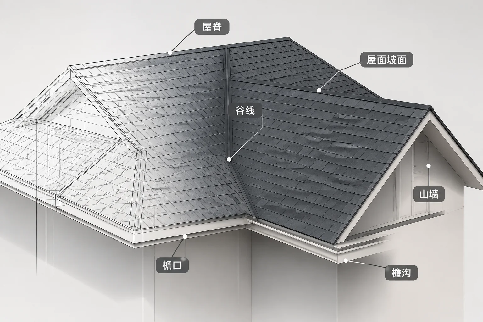
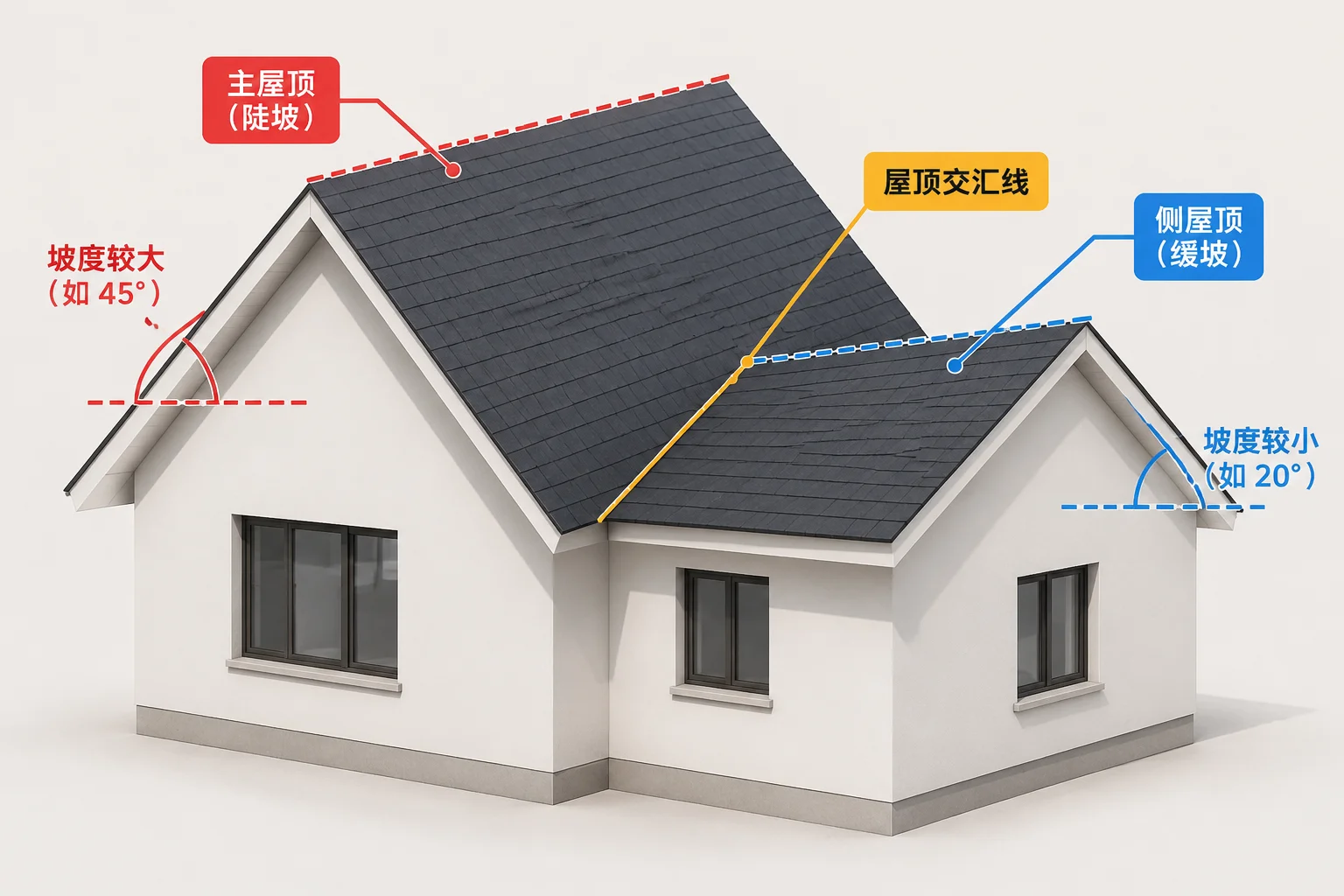
When evaluating intersecting pitched roofs, schematic drawings can look deceptively straightforward until disparate pitch slopes meet in three dimensions. In this illustrative study, a primary gable volume pitched at 6:12 is joined perpendicularly by a secondary lateral addition with a shallower 4:12 pitch. The central question is concrete: where exactly do these unequal planes intersect? This theoretical model exists not as a construction-ready blueprint, but as an educational exercise in reading planar lines, understanding asymmetrical valley vectors, and preventing framing layout errors.
Geometric Rule of Unequal Slopes
Because the lateral wing carries a shallower pitch (4:12) than the main gable (6:12), its ridge terminates into the sloping surface of the primary roof plane rather than meeting at a common apex. The resulting valley line skews toward the shallower plane in plan view, requiring strict verification of top plate heights and rafter seat cuts.
Deconstructing the Intersection Step by Step
On a 2D overhead diagram, many assume an intersecting perpendicular gable creates a symmetrical 45-degree valley angle. When pitches differ, that assumption collapses. Because the lateral roof rises only 4 inches per foot while the main structure climbs 6 inches, the valley path bends distinctly toward the lower pitch:
- Overhead Skew: The shallower 4:12 plane requires a longer horizontal run to achieve height, rotating the plan-view valley line off the standard 45-degree bisector.
- Secondary Ridge Termination: The lateral ridge dead-ends midway up the main roof slope, creating a high-stress water discharge point that demands meticulous cricket planning.
- Fascia Line Discrepancies: Equal overhang widths will produce mismatched soffit elevations unless wall plates are intentionally framed at different levels.
Transferring schematic lines into an isometric view reveals how the planes interact in physical volume. Plane A (the primary 6:12 slope) descends from the main ridge across a continuous pitch run. Plane B (the westward addition slope) meets Plane A along a diagonal space curve known as the valley rafter centerline. Annotating this drawing requires marking true rafter lengths, plumb bevel cuts, and the exact Z-axis elevation at the intersection terminus. Without these clear notes, framers risk miscalculating backing angles on the supporting valley rafter.
Vertical baselines dictate roof intersections just as much as pitch values. If the secondary lateral volume is built with a standard 8-foot ceiling while the main core utilizes 9-foot wall plates, the baseline offset drives the intersection coordinate even higher along the primary gable. Critical verification questions arise: Has the bearing wall height been aligned across both envelopes? Will the concentrated valley run require double valley rafters? How will attic ventilation cross through the unbroken 6:12 plane? These calculations must be resolved systematically during design analysis before any physical timber framing occurs.
Comments & Peer Reviews
No comments yet. Be the first to leave a constructive observation.
Leave a Constructive Comment