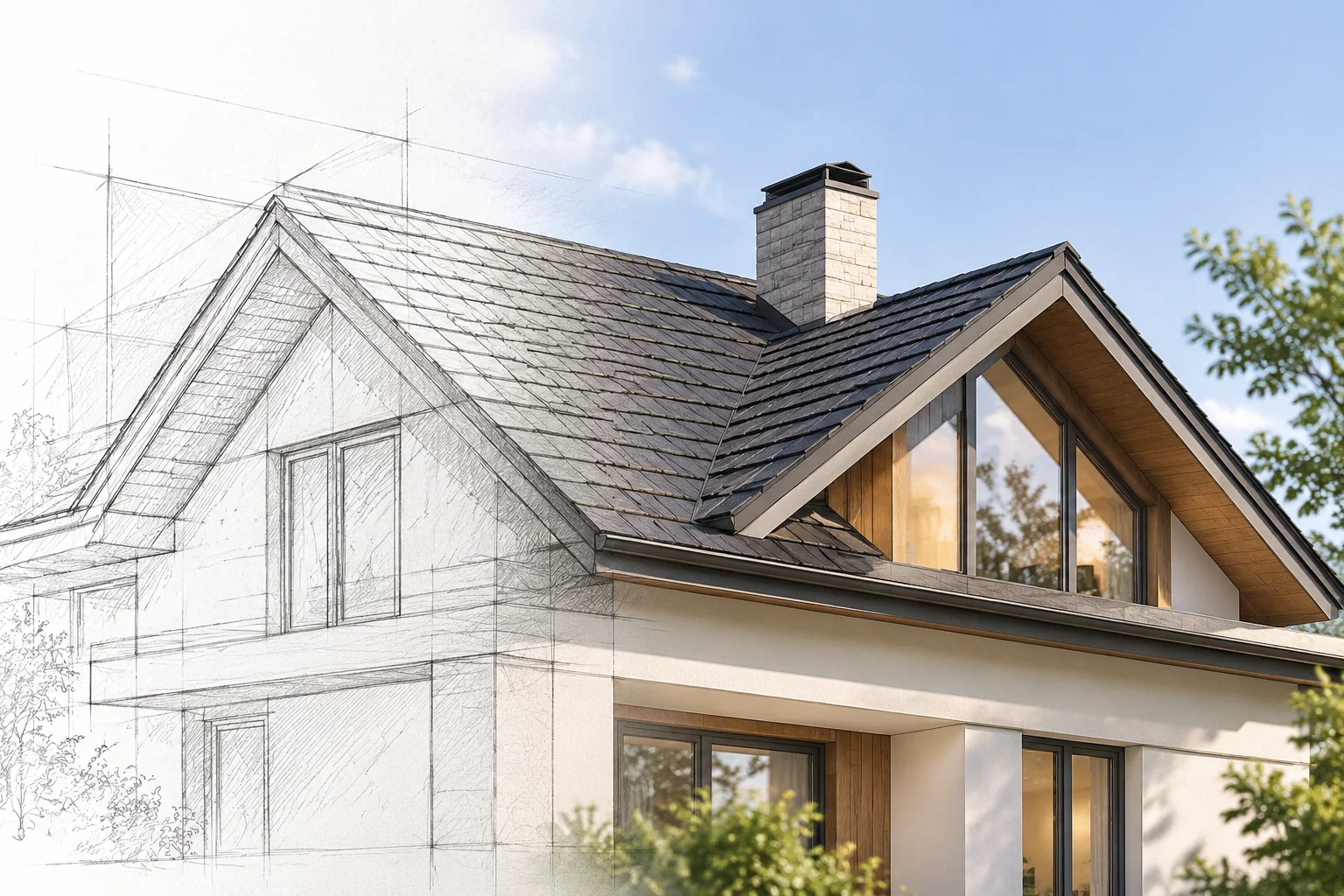
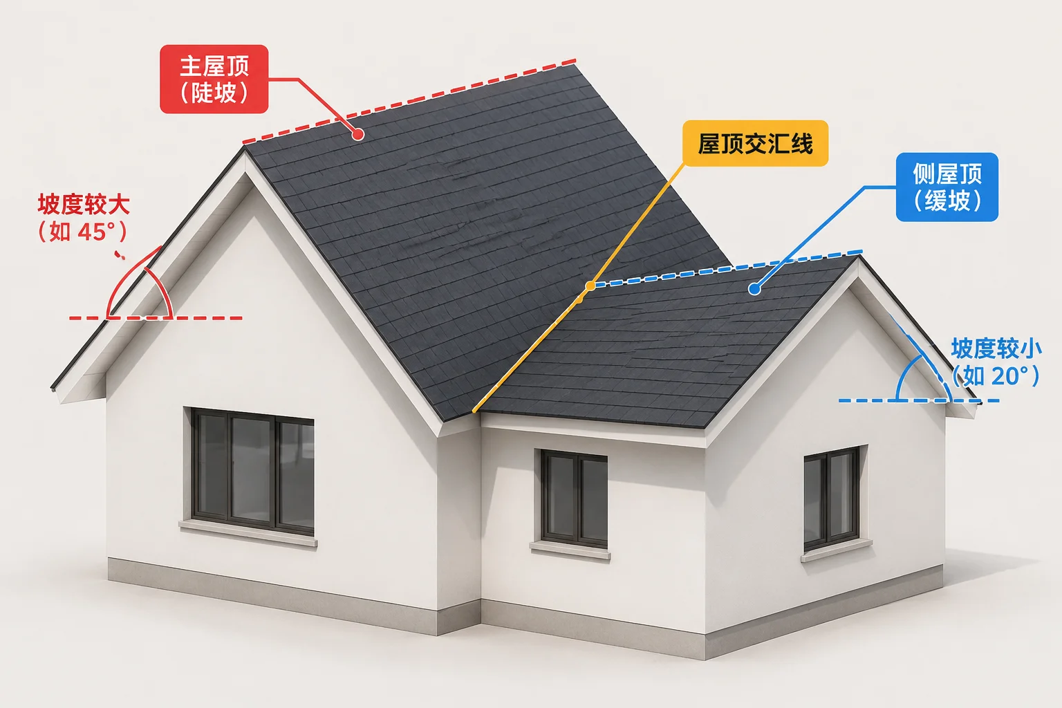
Initial conceptual sketches often depict intersecting roof forms with swift expressive strokes, yet building design requires every intersection line to be calculated down to the millimeter. This study analyzes a fictional single-family house where a main 6:12 pitch gable intersects a smaller lateral wing pitched at 4:12. The central question investigates where and how these differing planar slopes resolve into a continuous structural valley.
Core Technical Takeaway
When intersecting roof planes possess differing slopes, the resulting valley is inherently asymmetrical. The shallower 4:12 lateral plane rises more gradually than the steep 6:12 main slope, skewing the valley plan view toward the shallower side. These proportions represent pure geometric relationships rather than final structural dimensions and must never be treated as ready-for-construction blueprints.
Deconstructing the Intersection Geometry
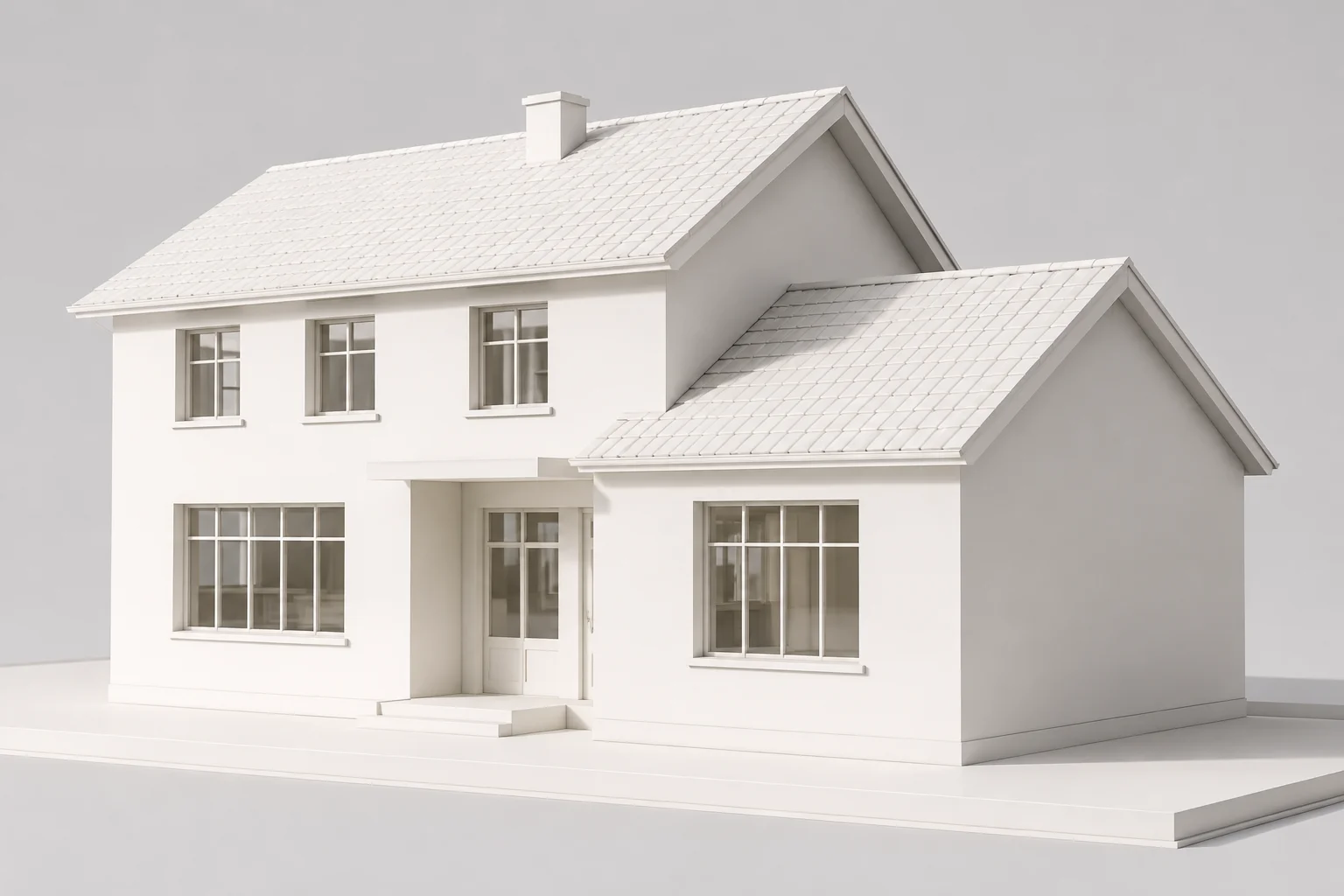
Freehand sketches tend to ignore wall plate height variations, assuming all ridge and eave lines automatically reconcile. Converting that concept into an accurate 2D plan view demands tracing the true baseline coordinates of each wall and calculating exact plane trajectories before attempting compound rafter layouts.
- Drafting accurate building perimeters to capture the physical footprint offset of the lateral volume.
- Calculating run-to-rise ratios for 6:12 (26.57°) and 4:12 (18.43°) slopes to plot precise intersection lines.
- Marking plate heights early to prevent unexpected discrepancies in vertical fascia alignment.
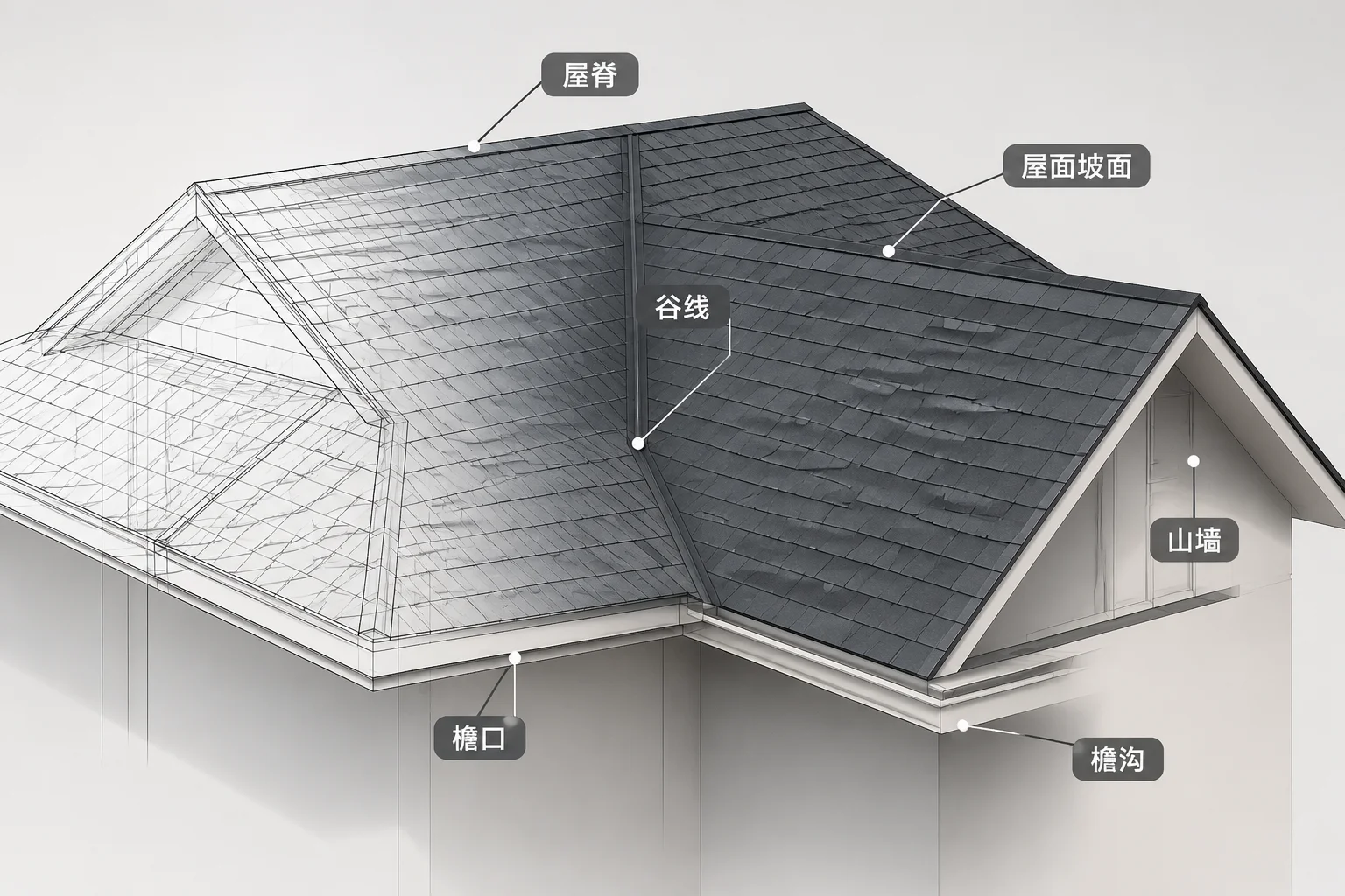
Isometric diagrams bridge the cognitive gap between flat 2D plans and complex three-dimensional roof space. In this study, annotating the secondary ridge reveals that because of its shallower pitch and narrower span, it terminates directly into the main roof field below the primary ridge line. Annotating both valley rafters and plane boundaries prevents automated modeling algorithms from generating erroneous blind dormers or twisted rake profiles.
Elevation adjustments produce dramatic shifts in roof valley position. Lowering the side addition top-plate elevation pulls the entire valley outward toward the exterior corner, while raising it pushes the intersection upward toward the primary ridge. Designers must document specific field verification items, including actual bearing wall heights, ceiling clearance beneath valleys, and overhang depth uniformity, before any cutting list is generated.
Comments & Peer Reviews
No comments yet. Be the first to leave a comment.
Leave a Constructive Comment