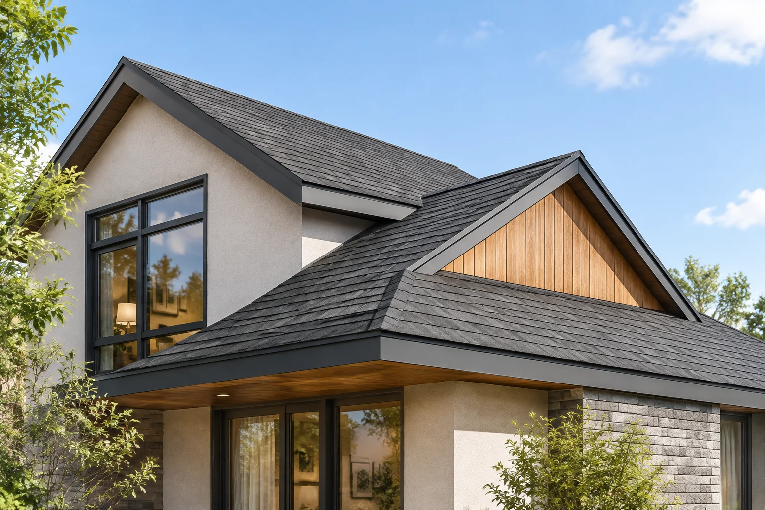
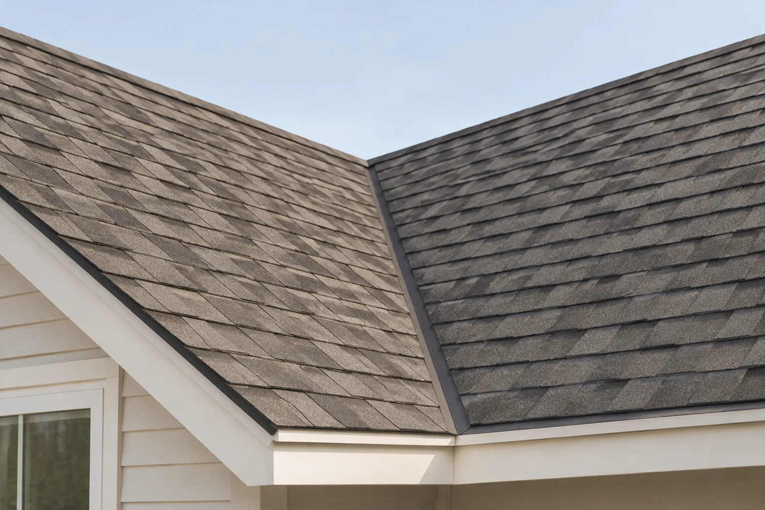
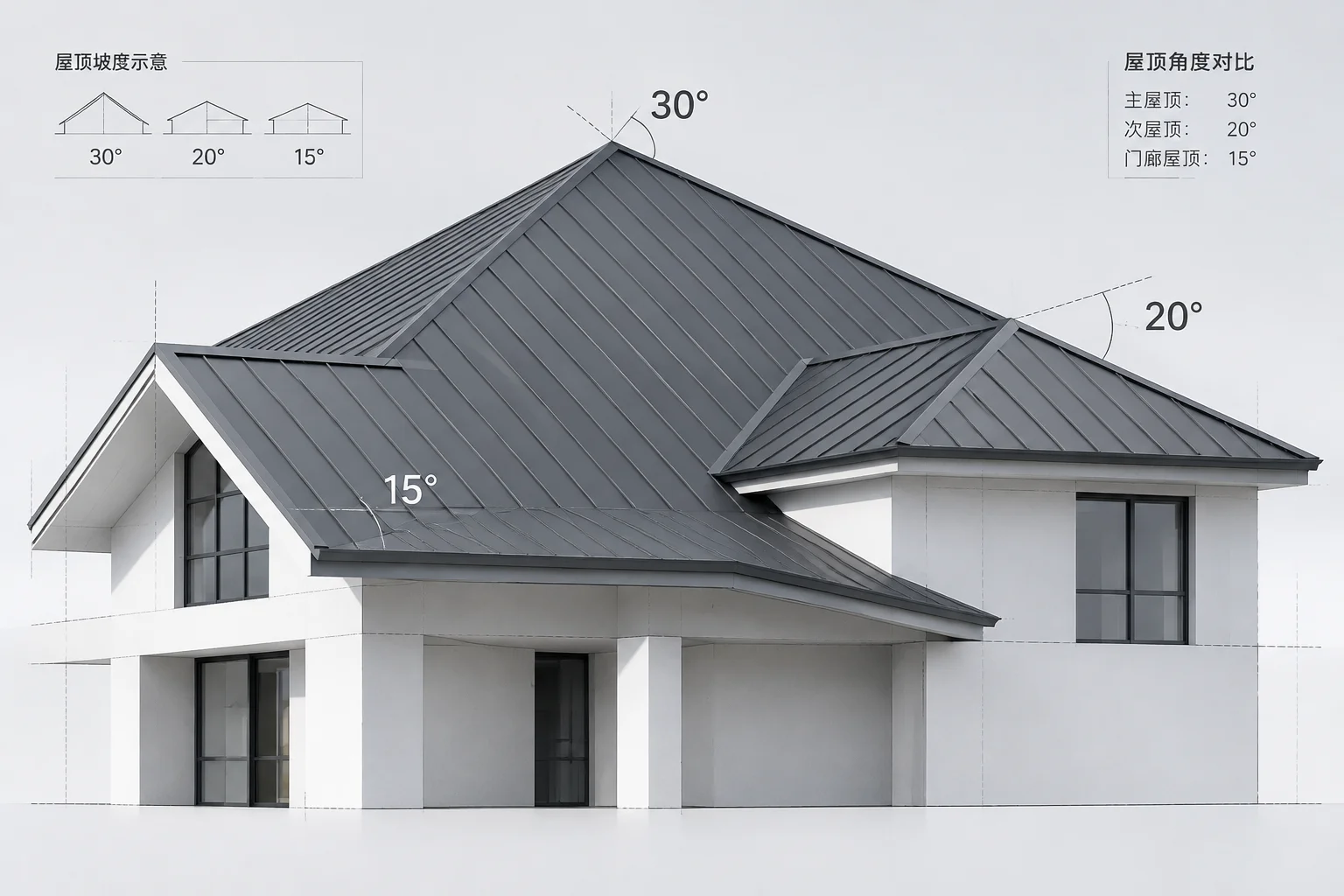
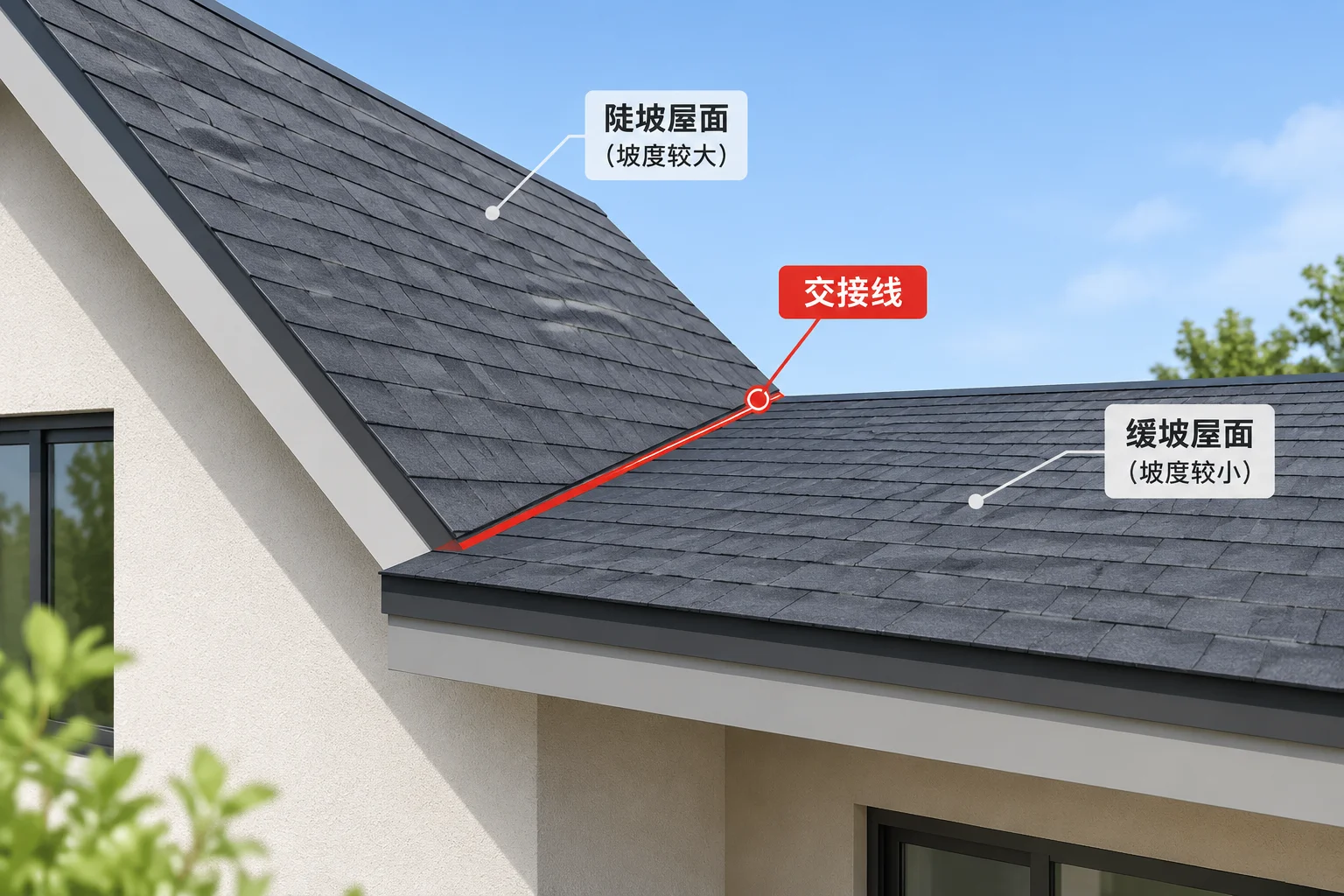
When two intersecting roof volumes sit on walls of differing heights or feature asymmetric baseline offsets, standard automatic roof tools often create unexpected compound valleys or misplaced ridges. In our illustrative educational model, a main 6:12 gable roof intersects with an added 4:12 lateral gable volume. Because their baseline elevations do not align, the horizontal projection of their valley departs from a clean 45-degree angle, forcing the lower ridge to die into the steeper plane at an asymmetrical coordinate.
Core Geometric Rule
Baseline alignment dictates where roof planes physically collide in 3D space. Whenever the plate heights differ or pitches vary, calculate plane intersection lines as simultaneous equations in coordinates (X, Y, Z) rather than relying on 2D footprint snapping.
Key Principles & Geometric Behavior
A roof baseline represents the elevation line where a rafter's pitch begins relative to the wall plate. When an addition or lateral wing has a baseline lower or higher than the primary structure, three immediate consequences occur:
- The valley line skews toward the plane with the shallower pitch and lower baseline run.
- The ridge of the subordinate volume terminates below the main ridge, requiring a valley sleeper or blind valley framing.
- Overhang fascia lines will fail to align horizontally unless wall plate heights are manually adjusted to compensate for pitch differentials.
In our educational scenario, the primary 6:12 gable rises at 0.5 feet per foot of run, while the secondary lateral 4:12 gable rises at only 0.333 feet per foot. If both roofs were to start at matching baseline heights, the valley would track at an angle whose tangent equals the ratio of the pitches (4 / 6 ≈ 0.667). However, shifting the lateral addition's baseline downward by even 6 inches shifts the starting node of the valley outward, creating an asymmetric diagonal that travels further along the main roof plane before terminating.
When drafting complex junctions in CAD or BIM, never assume auto-built roof valleys represent accurate framing cut lengths. Prepare a schematic plan view, an isometric cutaway, and cross-sectional elevations at the intersection node. Verify whether the truss chords require specialized scissor framing or structural valley boards to prevent moisture retention and load imbalances.
Comments & Peer Reviews
Tom B.
Architectural Drafter • 10/26/2026Baseline mismatch is a common issue, thanks for covering it.
Leave a Constructive Comment